

A Combination Valve is just what the name implies… a valve that does a combination of things. The problem is people get confused as to what is happening within the valve and what might be going on. With the information below, we hope some of this gets explained.
Many people will call this particular valve a Proportioning Valve. That isn’t necessarily 100% incorrect as a portion of the valve does perform that function. The proper and technical name for this valve is a Combination Valve.
To begin, we should discuss why it is called a Combination Valve. As we mentioned earlier, this valve does a combination of things and is made up of several different segments doing many different things. There is the Pressure Differential Switch and Valve, the Metering Valve and the Proportioning Valve. Read below to learn more.
Brake Pressure Differential Switch and Valve
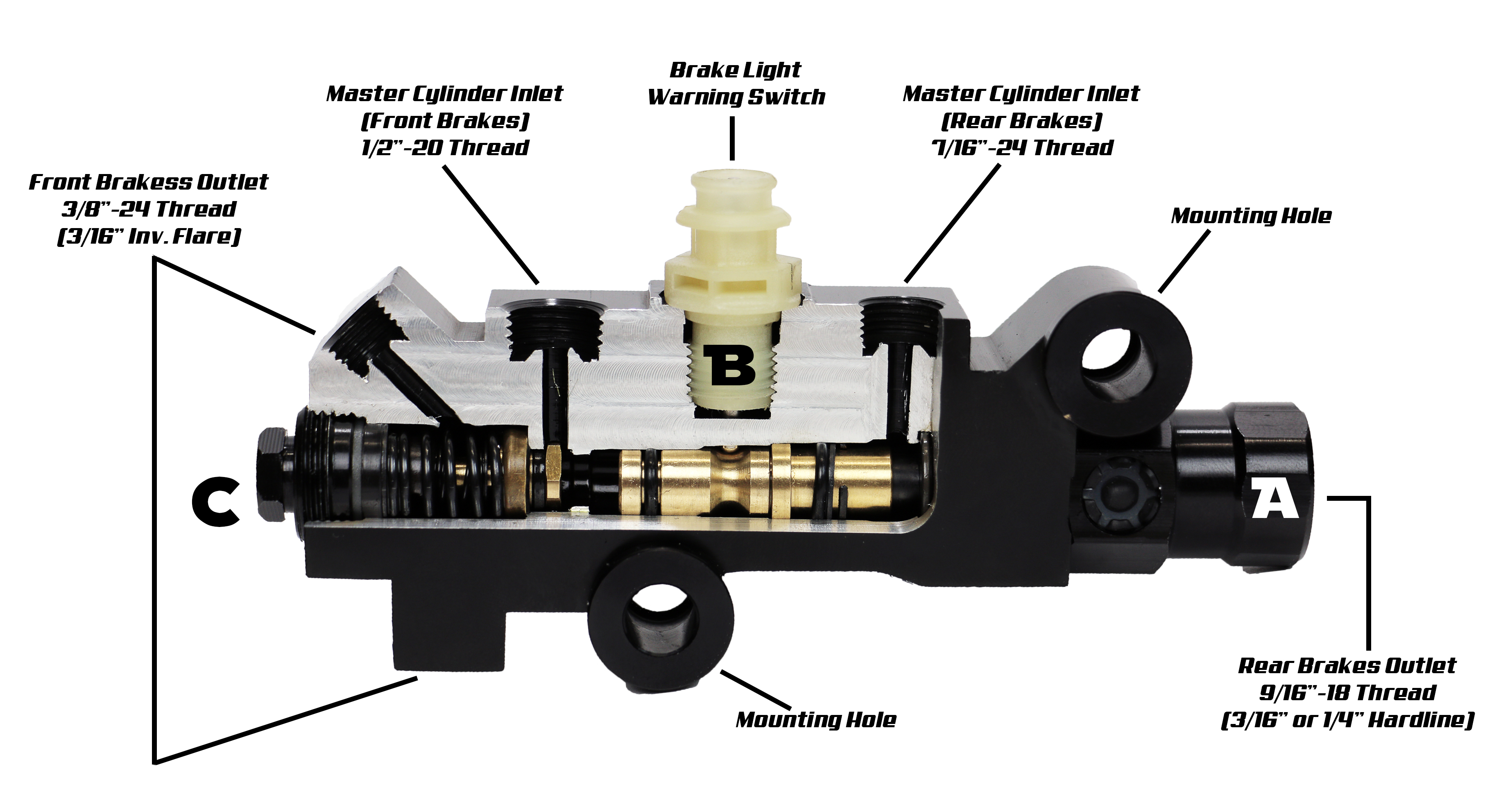
In the center of the Combination Valve (labeled as B in the image below) is a single wire connector that works in conjunction with a slide in the center of the valve. This portion of a Combination Valve is the first thing that sees brake pressure as generated by the master cylinder and is made up of two different components. There is the actual switch that works in conjunction with the Valve.
The purpose of this combination is to notify a driver should brake pressure be lost on either the front or rear brake system either before or after the valve. Should pressure be lost, the valve (which actually slides back and forth within the body of the combination valve) will close off either the front or rear of the valve which will provide an opportunity for a user to get home.
When this happens, the center pin on the switch will move and then ground the switch and turn on a light on your dash. This is a warning that something is wrong.
Metering Valve
At the front of the Combination Valve (seen below and labeled as C) if using a Combination Valve designated as disc/drum is the Metering Valve. The Metering Valve, sometimes referred to as a Hold-Off Valve, is used to regulate the pressure going to the front wheels when the brakes are initially pressed in a brake system using disc brakes in the front and drum brakes in the rear.
Due to the design of disc brakes versus drum brakes, disc brakes will apply quicker than drum brakes. If this happens, the car will nose dive when applying the brakes. To prevent this, the use of a Metering Valve is required. It will simply hold of the line pressure coming from the master cylinder ever so slightly allowing the rear brakes to apply first. The total time it holds off the front brakes is so slight that as a driver, it is never even realized.
The Metering Valve portion becomes less of a discussion when you have a vehicle with disc brakes on the front and rear. In this situation, you do not need a Metering Valve and therefore would by a Combination Valve designated as disc/disc. These valves basically have an open cavity internally in the front that basically allows equal line pressure at equal times to both the front and rear.
Proportioning Valve
The Proportioning Valve part of the Combination Valve (seen above and labeled as A) is used to control the rear brakes. What the Proportioning Valve does and when it actually works is one of the biggest misunderstandings in a Combination Valve. In a moderate braking situation, line pressure being generated by the master cylinder is less extreme and therefore will reach the calipers or wheel cylinders in full. However, when the brakes are really put to work and a panic stop happens, this is when the Proportioning Valve goes to work. In a panic stop, the Proportioning Valve will actually reduce the line pressure to the rear brakes in an effort to try and minimize rear brake lock-up and also the possibility of the rear of the car passing the front of the car which is never a situation anyone wants to experience.
When purchasing our VL3360K Combination Valve for disc/drum vehicles, you will notice an extra part included. It is a very simple brass plug.
Don’t throw this away!
Should you ever want to convert the car to disc brakes in the rear, we include a plug that will replace the Metering Valve. Simply locate the nut on the front of the valve, remove the Metering Valve, and replace it with the included plug. You now have a valve that will work with disc/disc combinations.
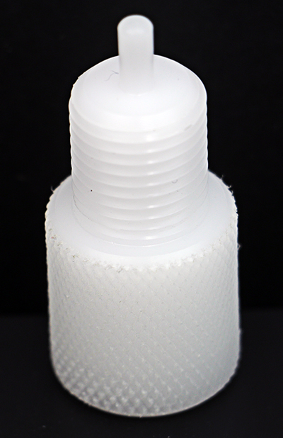
Also included in all Combination Valve Kits from MP Brakes is a somewhat unusual-looking white plastic part (HW3350). This part is a tool that should always be used when bleeding the brakes. This simple little tool will save a bunch of headaches by holding the slider in place and therefore not allowing the valve to become “tripped”.
Just like a brake pressure failure will cause the slider to move, the same can happen when bleeding fluid from the master cylinder to the rest of the system. Getting a valve “un-tripped” is always a challenge, so take the extra time to insert the tool. To find out more about this tool check out our Blog Post on how it works.
A Quick Note
When you look at the Combination Valve, you will notice two 3/8”-24 ports that both show going to the front brakes. You don’t have to use both or you can. The choice is yours. This will be based on the plumbing in the vehicle. If you want to use just one, plug the other and then “T” the front lines later in the system.
If you have additional questions about Combination Valves for your classic ride, be sure to check out our in-depth video below!
As always, if you have any questions about this post, don’t hesitate to leave us a message below, send us an email, or even give us a call. We will do everything we can to assist you in getting the proper information.